Advanced Flow Simulation in Hydraulics & Fluid Machinery
The performance of complex hydraulic systems and fluid machinery depends heavily on optimal flow distribution. Poorly managed fluid dynamics can introduce severe turbulence, flow separation, and vortex formation. In intake structures and process piping, these phenomena lead to air entrainment, excessive swirl, and uneven loading—the primary drivers of pump cavitation, structural vibration, and premature component failure.
CFD Validation of Pump Sump Intake Vortices and Air Entrainment against ANSI/HI 9.8 Standards
Objective: To validate the capability of multiphase Computational Fluid Dynamics (CFD) in capturing complex free-surface air-entrained vortices and subsurface submerged vortices within a standard open pump intake channel.
The simulation recreates the experimental domain established by Guo et al. (“Effect of suction pipe inlet condition on the occurrence of vortex in pump sump”) to evaluate critical water levels, asymmetric intake effects, and severe flow rotations. Furthermore, the numerical results are audited against the global industry benchmark, ANSI/HI 9.8 (Rotodynamic Pumps for Pump Intake Design), to assess hydraulic acceptability for real-world engineering infrastructure.
Numerical Methodology & Air Entrainment Capture
To accurately capture the sharp, transient air-water interface of the free-surface dimple and air-entrained core, a high-fidelity multiphase model was deployed:
Multiphase Framework: Volume of Fluid (VOF) formulation tracking the volume fraction of the air and water phases.
Turbulence Modeling: Shear Stress Transport (SST k-omega) model to resolve high-velocity gradients, severe shear layers, and localized pressure drops near the suction bell mouth.
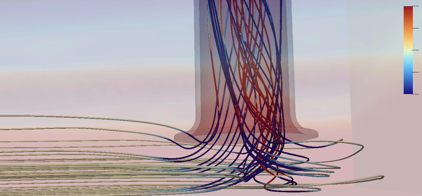
Vortex Identification: Iso-surfaces of Q-criterion or Vorticity colored by velocity magnitude were utilized to map the geometric path of the air-entraining core stretching from the free surface directly into the pump’s suction line.
Results Match: In alignment with Guo et al.’s findings, the model successfully demonstrated that under critical low submergence (H) and elevated flow rates (Q), the localized core pressure drops below atmospheric levels, pulling a sustained filament of air into the pipe.
The CFD model successfully captured a swirl angle of 6.2°, confirming the presence of strong pre-swirl rotation induced by the asymmetric boundaries outlined in Guo’s experimental layout (85 mm vs 115 mm wall clearance). Because this exceeds the 5° industrial threshold, this specific case perfectly demonstrates how the CFD model functions as a diagnostic tool—flagging non-compliant hydraulic conditions before structural fabrication begins.
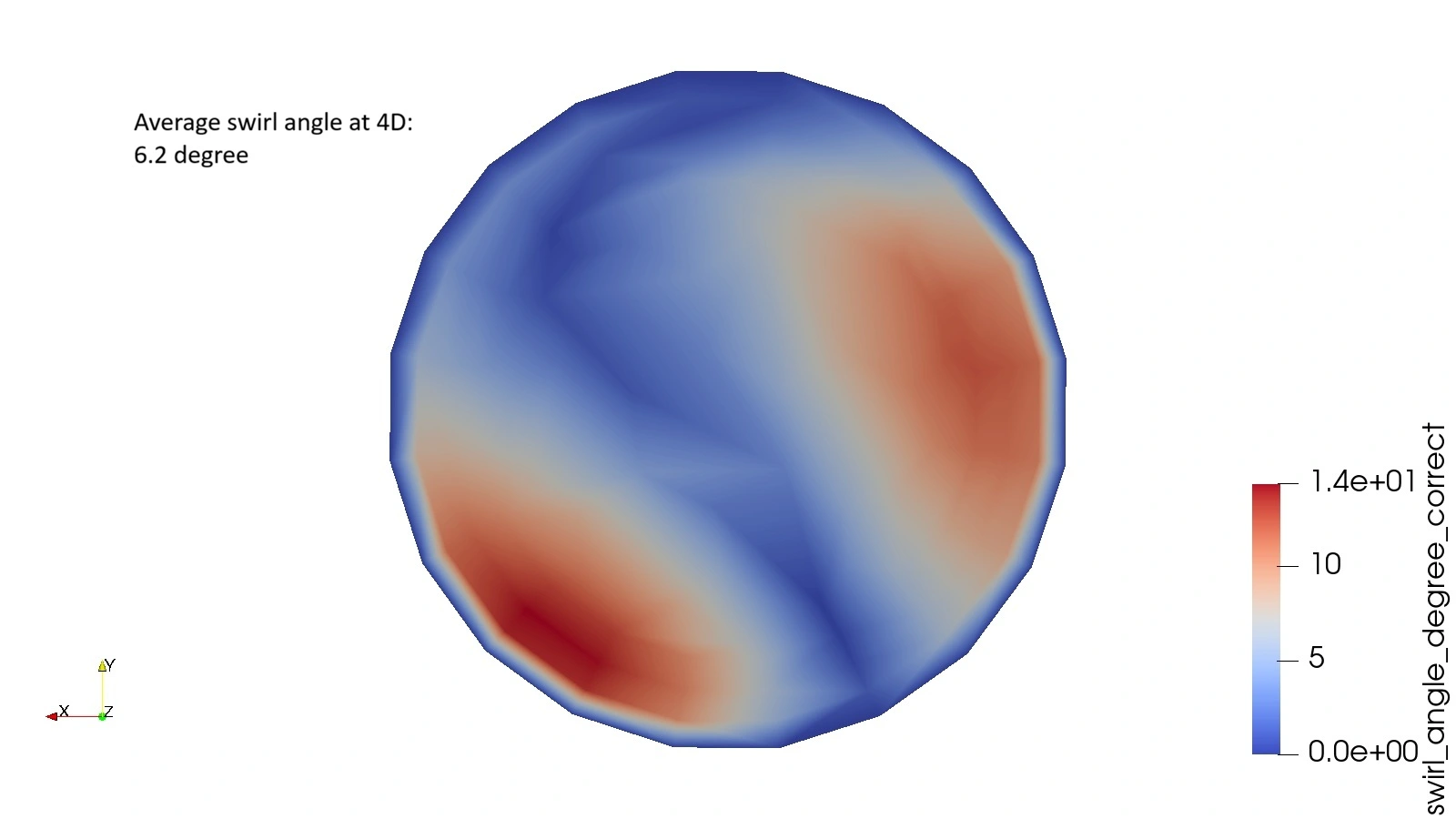
ANSI/HI 9.8 Swirl Angle Criteria
According to the ANSI/HI 9.8 (Rotodynamic Pumps for Pump Intake Design) standard, evaluating flow rotation within the suction pipe is critical to safeguarding the pump impeller from premature wear, cavitation, and hydraulic instability.
To ensure an acceptable velocity profile, a velocity meter or numerical cross-section measurement must be analyzed at a distance of exactly 4D (four times the suction pipe diameter) upstream from the suction bell entrance. The standard dictates that the calculated swirl angle must not exceed 5°.
Where:
- θ (Theta) = Calculated swirl angle (degrees)
- Vθ (V-theta) = Average tangential (circumferential) velocity component across the 4D pipe cross-section
- Vz (V-z) = Average axial velocity component across the 4D pipe cross-section