Performance Validation of a Shell and Tube Heat Exchanger
Overview
This project presents a high-fidelity Computational Fluid Dynamics (CFD) study of a shell and tube heat exchanger, modeled to evaluate thermal-hydraulic performance in practical cooling applications. The simulation is based on the experimental framework detailed in the study “Design, Fabrication and Performance Evaluation of a Shell and Tube Heat Exchanger for Practical Application,” allowing for a direct comparison between numerical results and physical performance data.
Technical Methodology
To ensure an accurate representation of the complex flow physics within the shell, the simulation utilized a single-phase, steady-state model focused on the cooling of high-temperature process water.
Key modeling parameters included:
Turbulence Modeling: The k−ω SST (Shear Stress Transport) model was selected for its superior ability to handle adverse pressure gradients and flow separation—critical for capturing the secondary flows and vortices around the baffles.
Near-Wall Treatment: A high-quality boundary layer mesh was implemented on all solid-fluid interfaces. This refined inflation layer ensures accurate calculation of the velocity and temperature gradients, which are essential for predicting the convective heat transfer coefficient and overall pressure drop. To ensure the k−ω SST model accurately predicts the convective heat transfer coefficient, the near-wall mesh was refined to maintain a y+ value near 1, allowing for the direct integration of the flow through the viscous sublayer.
Dimensionless Wall Distance (y+):
Results Validation
The following data compares the CFD exit temperatures against the experimental benchmarks, demonstrating the high degree of accuracy achieved by the k−ω SST turbulence model. Utilizing OpenFOAM for this validation highlights the solver’s robust handling of the k−ω SST equations, offering significant computational speed advantages and scalability for high-cell-count models compared to traditional commercial alternatives.
| Trial | Shell Outlet Temp (°C) | Tube Outlet Temp (°C) | Relative Error (%) | |||
|---|---|---|---|---|---|---|
| EXP | CFD | EXP | CFD | Shell | Tube | |
| 1 | 59.3 | 59.2 | 47.6 | 47.4 | -0.17% | -0.42% |
| 2 | 61.0 | 61.1 | 50.6 | 50.8 | 0.16% | 0.40% |
| 3 | 63.0 | 62.9 | 53.6 | 53.7 | -0.16% | 0.19% |
| 4 | 65.2 | 65.3 | 56.5 | 56.6 | 0.15% | 0.18% |
| Highly accurate CFD results (Error < 0.5%) | ||||||
Thermal Analysis: From Local Gradients to Global Design
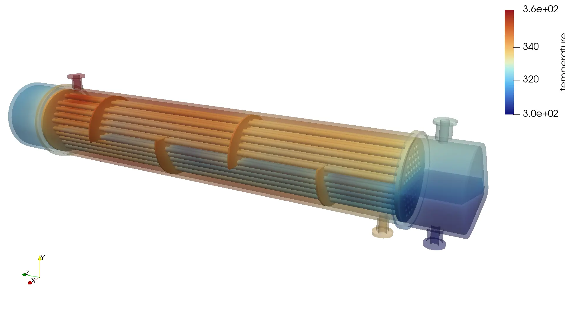
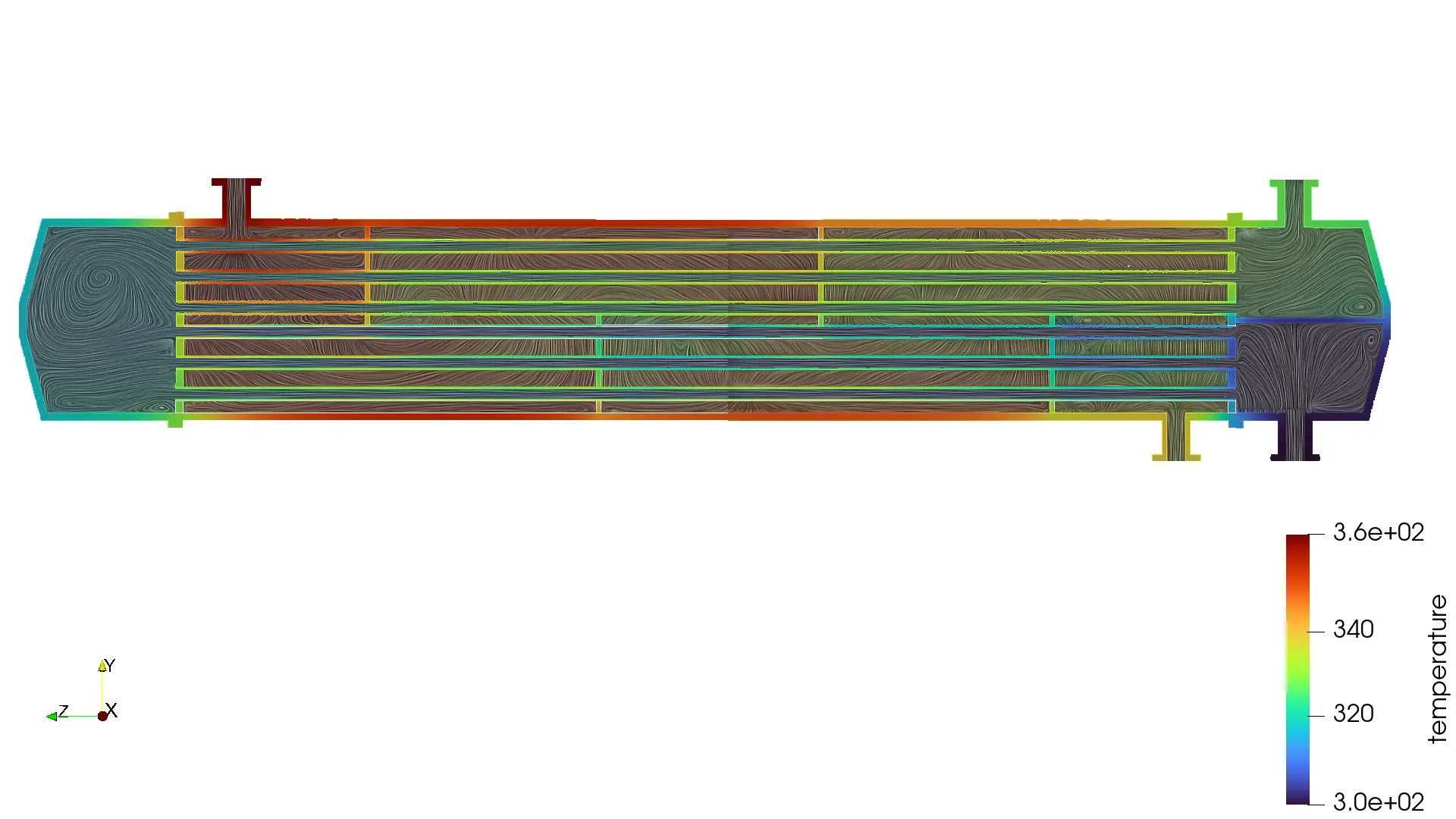
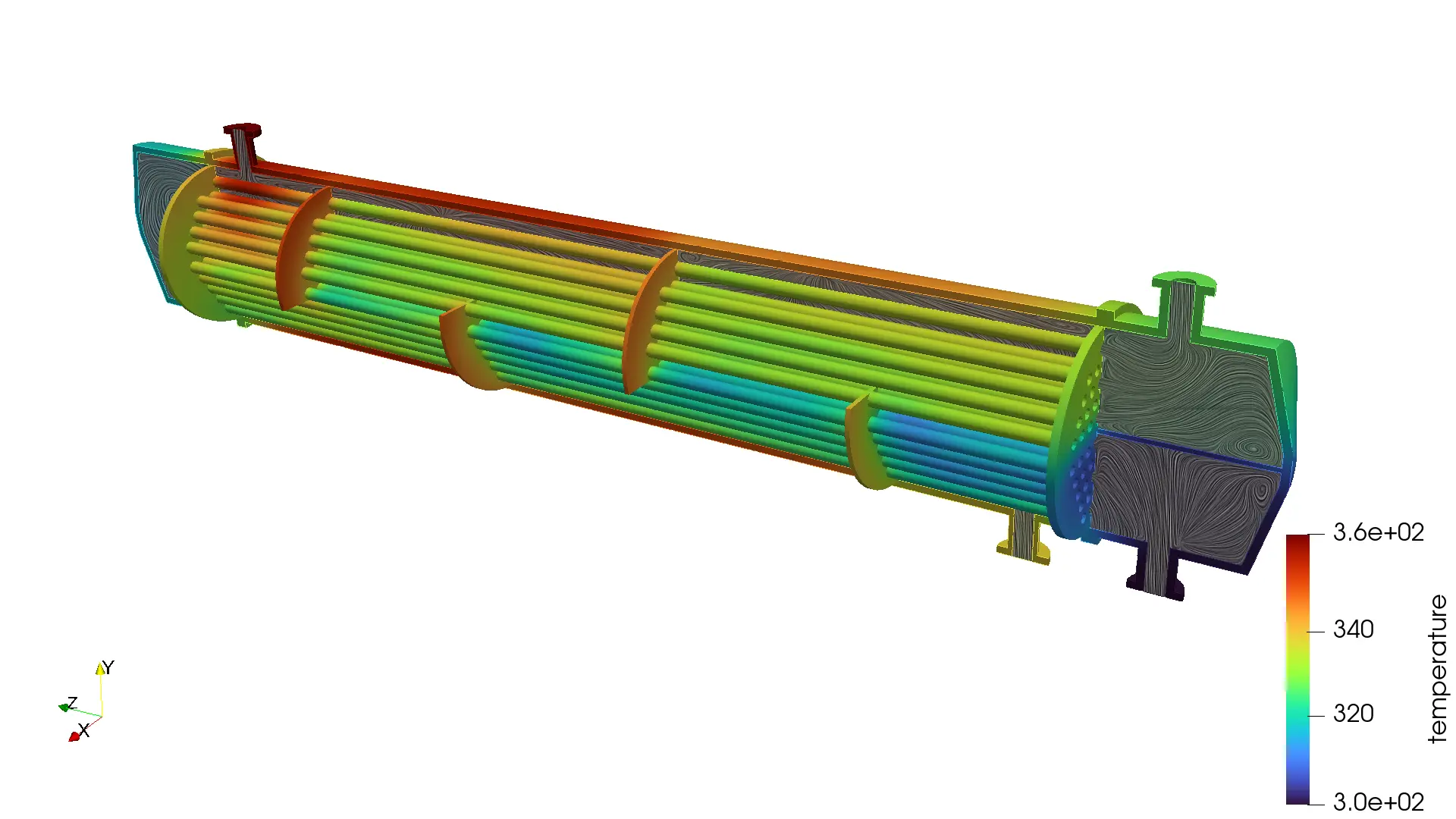
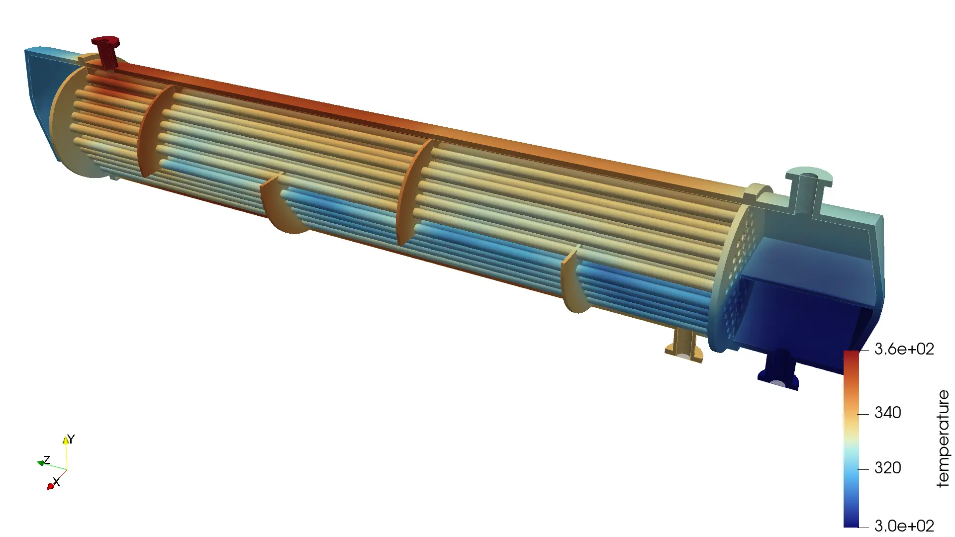
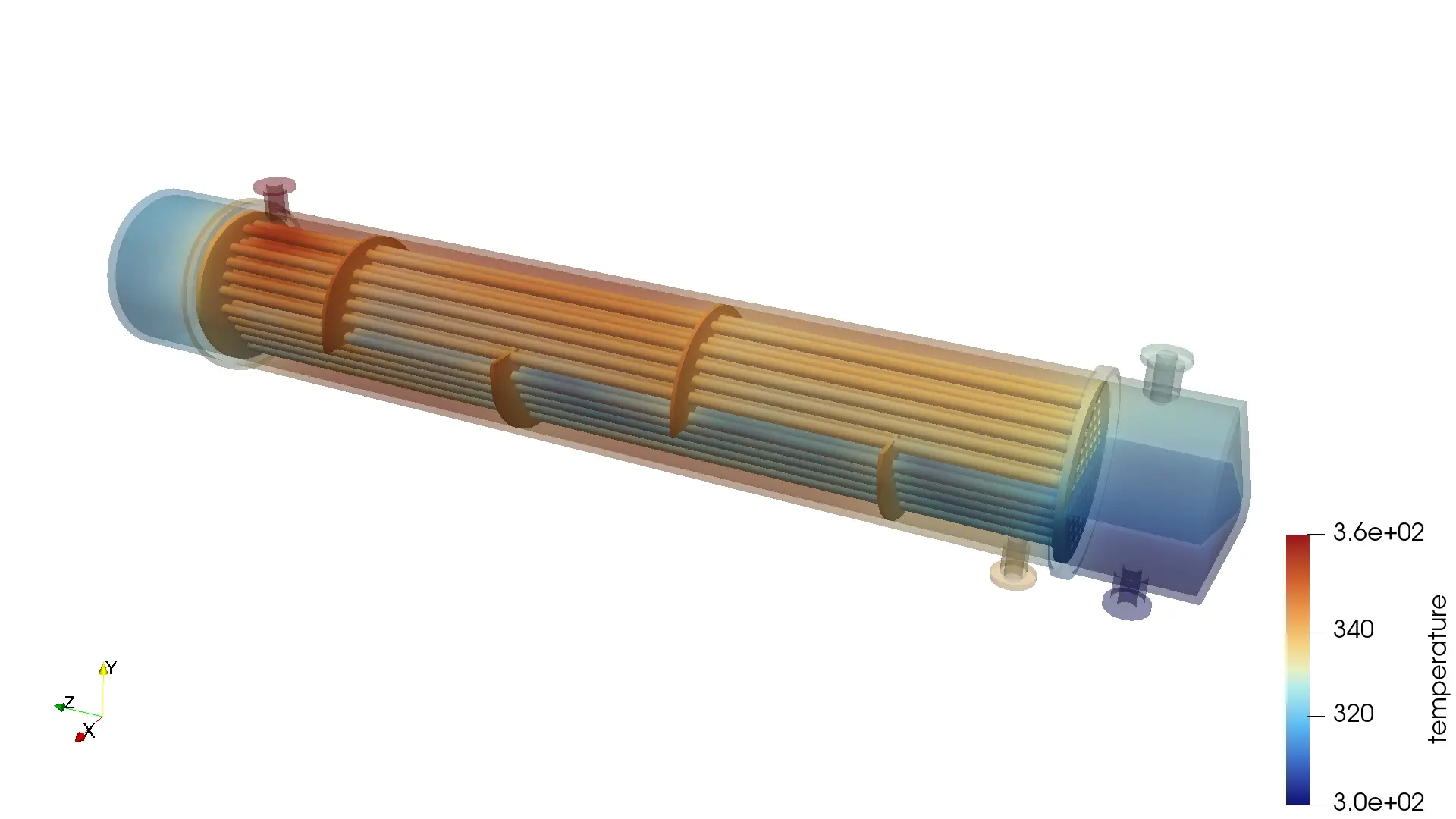
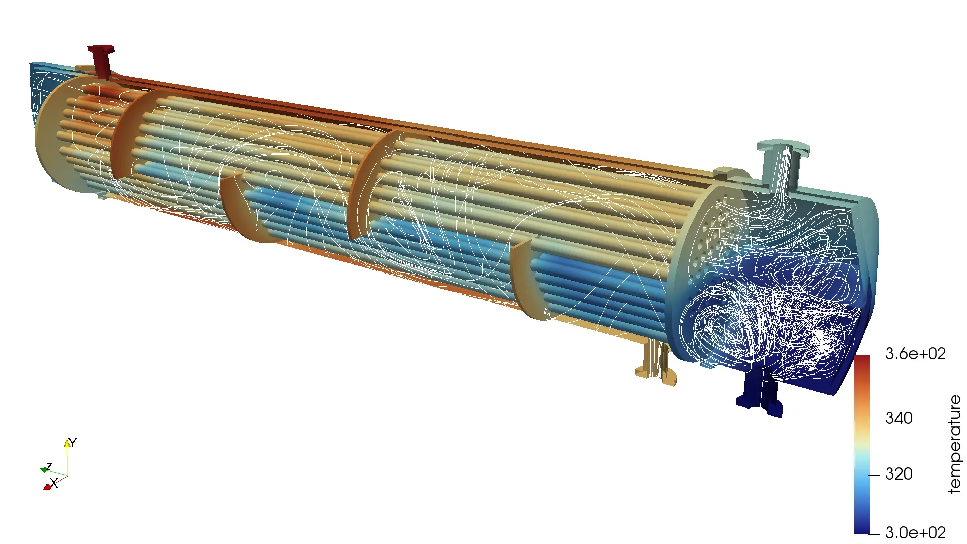
The thermal performance of a shell and tube heat exchanger is governed by the relationship between the convective heat transfer coefficient (h), which depends on local flow characteristics, and the overall heat transfer coefficient (U), which accounts for the combined thermal resistance of both fluids and the tube material. In industrial design, these parameters are critical for determining the heat duty via the Logarithmic Mean Temperature Difference (LMTD) method. While traditional empirical correlations provide a bulk estimate of U, the CFD results offer a significantly higher resolution of the temperature distribution. By visualizing temperature contours and streamlines, engineers can identify stagnant zones or bypass flows that reduce the effective surface area. These high-fidelity insights allow for the precise tuning of U and LMTD calculations, ensuring that the final equipment design is neither under-engineered (leading to thermal failure) nor over-engineered (leading to unnecessary capital costs).
These contours display the temperature distribution and flow streamlines predicted by the CFD model.
Heat Exchanger Analytical Framework
Energy balance, LMTD and Overll heat transfer coefficient.
1. Global Energy Balance:
2. General Heat Transfer:
3. Logarithmic Mean Temperature Difference (LMTD):
4. Overall Heat Transfer Coefficient (U):